6.5. Spatial frames and TF2#
A robotic system typically has many 3D coordinate frames that change over time, such as a world frame, base frame, gripper frame, head frame, etc.
This such a common and import task for a robotic system that ROS provides a special library, tf2 to help nodes keeps track of all these frames over time.
It allows you to ask questions like:
Where was the head frame relative to the world frame 5 seconds ago?
What is the pose of the object in my gripper relative to my base?
What is the current pose of the base frame in the map frame?
To be more specific, a frame is a 3D coordinate system, with an origin, and three principal orthogonal directions using the right-hand convention, with X forward, Y left, and Z up. A frame by itself does not have a location, it can only be used to express other points in space relative to it. Hence, a frame’s location and orientation is only meaningful when expressed with respect to another frame.
This is what we call a transformation: the proper rigid transformation between A -> B expresses the translation and rotation of frame B relative to frame A.
If we know this transformation we can convert any 3D frame in frame A to its corresponding 3D coordinates in frame B, and vice versa.
Thus, only with a known transformation A -> B or B -> A can we meaningfully talk about “the location” of frame B with respect to frame A, since we could convert B’s (0,0,0) coordinate to some (x,y,z) coordinate in A.
6.5.1. What is tf2#
tf2 is the transform library, which lets the user keep track of multiple coordinate frames over time.
When you develop a node that needs to process spatio-temporal information about the (dynamic) world,
tf2 provides a standardized way to maintain the relationship between all coordinate frames in a tree structure, buffered in time and lets the programmer transform points, vectors, etc. between any two coordinate frames at any desired point in time.
It does this by providing basic geometry data types, such as Vector3, Matrix3x3, Quaternion, Transform,
and supporting linear algebra operations needed to apply the transformations.
tf2 is designed to operate in a distributed system.
This means all the information about the coordinate frames of a robot is available to all ROS 2 components on any computer in the system.
Every component in your distributed system that uses tf2 will build its own transform information database or have a central node that gathers and stores all transform information.
This is done by subscribing to two topics that are specially reserved for the tf2 library, namely /tf and /tf_static.
6.5.2. Example use cases#
Here are some example use cases:
A robot has a single frame which is used to represent its “origin” or “location”. The convention is to call this frame
base_link. It defines where we will express the physical (0,0,0) coordinate is relative to the robot, what its “forward” (X), “left” (Y) and “up” (Z) directions are. When sensors are mounted on the base, e.g. a camera or LiDAR on a mobile robot body, we need to extrinsically calibrate their frames, i.e., determine where the sensor frames are located relative tobase_link, and what direction they are pointing too. Calibration thus expresses several transformations between the base and the sensor, e.g. frombase_link -> camera. Such extrinsic calibration parameters are usually set when developing the hardware, and regularly updated using calibration tools for the most accurate results. However during operation such calibration parameters would not change, and can therefore be considered static: once we know them, we don’t need regular updates.A robot can also have articulated components, such as an moveable arm. The arm can consist of multiple links which can move independently, such as a shoulder, elbow and a gripper. Each link will have an associated coordinate frame, where there is hierarchy: if we rotate or translate the elbow, it would also indirectly also affect the coordinate frame of the gripper, even if the joint between the elbow and gripper remained fixed. We need to track how the frame of each link dynamically changes over time, as we control the joints. This is often done via proprioceptive sensors in the motors, which should be converted to updated transformations between the frames.
For a mobile robot, we often need to keep track where the robot’s base
base_linkis located within some knownmapframe. The robot’s navigation stack is therefore responsible to continuously re-estimate the robot’s location, and publish amap -> base_linktransformation. If we have multiple maps in a physical world, e.g. for an outdoor vehicle or drone, it may even be important where this map is in the world with aworld -> mapframe.
6.5.3. Coordinate Frame Conventions#
An important part of using tf2 is to use standard conventions for coordinate frames. There are several sources of conventions for using coordinate frames.
Units, orientation conventions, chirality, rotation representations, and covariance representations are covered in REP 103.
Standard names for mobile base coordinate frames are covered in REP 105.
Standard coordinate frames for Humanoid Robots are in REP 120.
For definitions of some of the math terms used please see the /Terminology page.
Coordinate frames in ROS are identified by a string frame_id in the format lower case underscore separated. This string has to be unique in the system. All data produced can simply identify it’s frame_id to state where it is in the world.
We already saw in Section 5.7.4 that the frame_id is part of the stds_msgs/msg/Header message type, which is included in many other message types that represent spatio-temporal information for the robot.
6.5.4. Example of frame_id: RViz and a Marker#
RViz also uses tf2 to figure out where to render its display’s in the center 3D view.
To show 3D content, RViz requires you to select a reference frame, configured using Fixed frame in its Global options in the bar on the left.
When receiving messages for its display’s, RViz will use tf2 to transform the spatial information in the message from the message’s frame_id (found in the header of the message) to the target reference frame.
RViz also provides a display to visualize the origin and orientation of all known frames relative to its target frame,
and to visualize the frame hierarchy.
It is therefore an excellent tool to start exploring frames.
Let’s go back to the MarkerArray example from Section 6.4.4,
and repeat it those steps. So, if you did not do so already:
Open RViz, and ensure its fixed frame is set to
map.In another shell, use ROS’s
topic pubcommand to publish the markers in the filemarkerarray.yamlVerify you can see the 3D shapes in RViz again.
The MarkerArray contains a list of three Marker messages, each with their own header and thus a frame_id.
To check the frame_ids that we publish, we can simply check what value is set in the used YAML file.
Let’s use our go-to shell tool to scan for lines in a file, grep, using the syntax grep <string-to-search> <filename>:
$ grep "frame_id" ./markerarray.yaml
      frame_id: "map"
      frame_id: "map"
      frame_id: "map"
The output shows us that the three frame_ids all use the map frame too.
Exercise 6.5
Now let’s change RViz’s reference frame to something else.
Edit the Fixed frame option in Rviz, and set it to world.
The three 3D shapes disappeared!
Perhaps this should not surprise us: RViz cannot display the markers anymore,
because it does not know the transformation between its world reference frame, and the map frames in which the marker geometry is defined.
You can also see this confirmed through a red Status: Error in RViz’s MarkerArray display.
To solve this, we will need a node that publishes a world -> map or map -> world transformation.
6.5.5. Publishing transformations using tf_tools#
The tf2_ros package contains static_transform_publisher, a simple node that can be used to publish a single non-changing transformation between two frames.
Let’s use it to define the missing world -> map transformation for all ROS nodes.
$ ros2 run tf2_ros static_transform_publisher 1 2 3 0.5 0.1 -1.0 world map
This will publish a static transform from the parent frame world to the child frame map with (X, Y, Z) translation (1, 2, 3) in meters
and (yaw, pitch, roll) body-fixed axis rotation sequence (0.5, 0.1, -1.0) in radians.
After running the command above, we see a new ROS node is created which is publishing a static transform (check with ros2 node list).
It will keep running until it is killed.
Exercise 6.6
Look at the RViz windows again. Our 3D marker shapes returned, but they are now somewhat shifted and at a weird angle!
That is because we are viewing the scene from the world frame perspective, and the above transformation to map contains a translation and rotation.
We can see this more clearly by configuring some more displays in RViz:
Add a TF display (you need only one, so only add it if you didn’t add one before). In that display’s option, check the Show Names checkbox, and increasing the Marker Scale to 2. You should see a pair of 3D axes representations, showing the red, green and blue the cardinal directions x, y and z. The axis at the center of the RViz view is labeled with our fixed frame
world, the other frame between the markers asmap.Add a second
Griddisplay (there is already a defaut one below the Global Options), and for this second Grid set its Reference frame option to map. This will visualize the xy-plane at z = 0, which should be shown at an angle and aligned with themapaxes.
It should roughly look like this:
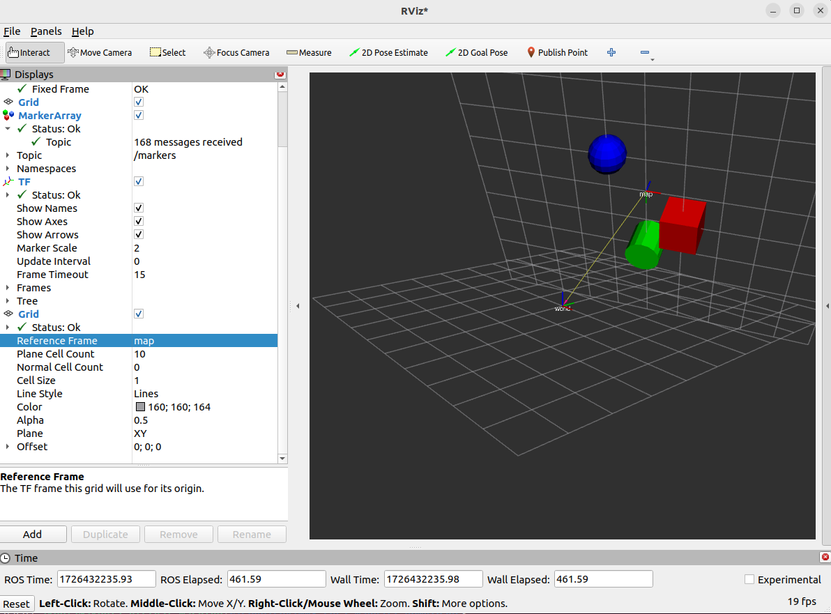
If you set RViz’s Fixed frame back to map, you will see that we are now viewing the scene again from the original view point,
and the 3D axes of map are now at the center.
6.5.6. Inspecting transforms from the CLI#
We don’t need to have RViz running and configured to get check if tf2 transformations are present.
The tf2_ros package also has a tf2_echo tool to report the transform between any two frames broadcasted over ROS.
To see if there is a known path through the frame hierarchy from a frame source_frame to a frame target_frame, you can use:
$ ros2 run tf2_ros tf2_echo [source_frame] [target_frame]
It will report the translation and rotation between these frames, as the tf2_echo listener receives the broadcasted frames over the /tf and /tf_static topics.
If there is no path in the frame hierarchy between these frames, it will tell you too.
Let’s look at the transform of the world frame with respect to map frame which is equivalent to:
$ ros2 run tf2_ros tf2_echo world map
[INFO] [1726432417.630013021] [tf2_echo]: Waiting for transform world ->  map: Invalid frame ID "world" passed to canTransform argument target_frame - frame does not exist
At time 0.0
- Translation: [1.000, 2.000, 3.000]
- Rotation: in Quaternion [-0.475, -0.076, 0.240, 0.843]
- Rotation: in RPY (radian) [-1.000, 0.100, 0.500]
- Rotation: in RPY (degree) [-57.296, 5.730, 28.648]
- Matrix:
  0.873 -0.333 -0.356  1.000
  0.477  0.434  0.764  2.000
 -0.100 -0.837  0.538  3.000
  0.000  0.000  0.000  1.000
Press CTRL-C to stop the listener.
Notice how the report Translation and Rotation in RPY (radian) relate to the arguments you give to the static_transform_publisher.
6.5.7. Creating an overview graph#
Another useful package is tf2_tools,
which contains the view_frames program which will create a visual diagram of the frames being broadcast by tf2 over ROS,
and saves it as a PDF file.
$ ros2 run tf2_tools view_frames
You will see:
Listening to tf data during 5 seconds...
Generating graph in frames.pdf file...
Here a tf2 listener is listening to the frames that are being broadcast over ROS and drawing a tree of how the frames are connected.
To view the tree, open the resulting frames.pdf with your favorite PDF viewer.
6.5.8. Defining a robot’s frames with URDF#
Setting up a whole bunch of static_transform_publishers is not really practical for a real robot.
Instead, it is more practical build a single unified robot description which describes the physical layout of the robot,
including its physical parts, their joints, and the names of the relevant coordinate frames.
We can do this with an Unified Robotics Description Format (URDF) file,
which describes all the robot’s components using XML syntax.
A URDF file can be read by a robot_state_publisher node, which does a few things for us:
It publishes the URDF’s XML integrally on a
/robot_descriptiontopic, such that other nodes and tools can read it if necessary. This includes RViz, which can use the description to show a 3D model of the robot.It will listen on the topic
/joint_statesfor the latestsensor_msgs/msg/JointStatemessages, which provide it with a information of the physical states of the robot’s dynamic joints.With the static frame transformations in the URDF, and the joint information from the URDF and
JointStatemessages, it can compute all the transformations between the robots frames, and publish these on the regulartf2topics/tfand/tf_static
So where do we get JointState information from?
In a real-world use case this would probably be provided by your own control nodes or motor driver nodes,
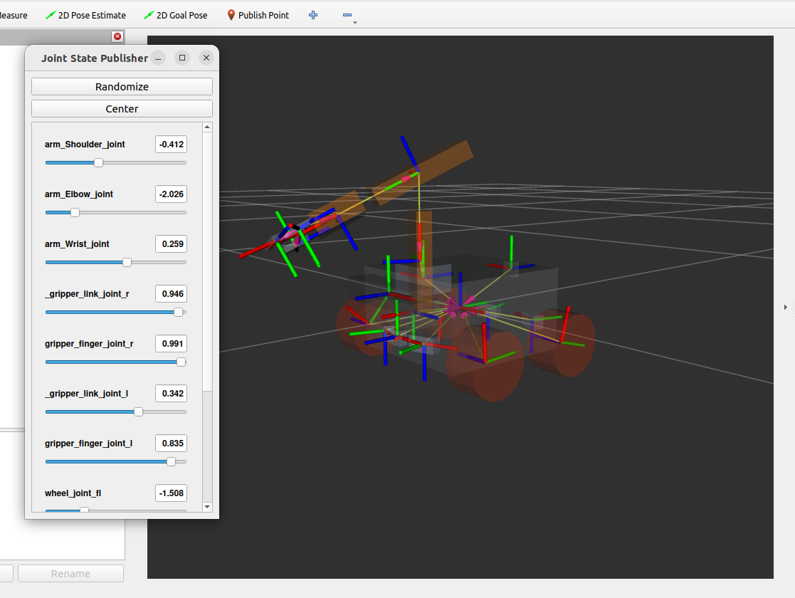
but for debugging and learning we can make use of the handy joint_state_publisher_gui package.
The node in this package will listen for the URDF on /robot_description, make a list of all moveable joints, and produce a very simple GUI to set values for those joints and publishes them as JointState messages.
Let’s try it out.
Download
mirte_master_simple.urdf, and save it in your working directory (right click, use Save Link As …)Start
robot_state_publisherin the package of the same name, and point it to where your URDF file. If it is in your working directory, you can simply useros2 run robot_state_publisher robot_state_publisher ./mirte_master_simple.urdf
In another terminal, start
joint_state_publisher_guiin the package of the same nameros2 run joint_state_publisher_gui joint_state_publisher_gui
Now start RViz, and configure several Displays:
In the Global Options display, set Fixed Frame to
base_linkAdd a single TF display, if it is not there yet. In the display options, you can
enable the Show names to display frame names
change the Marker scale of the frames to a smaller value, if they 3D axis display is too big
Add a single RobotModel display, if it is not there yet. In its display options,
make sure its Descrition Topic is set to
/robot_descriptionyou can set Alpha transparency to a value between 0 and 1, e.g. 0.7, to better see the tf frames
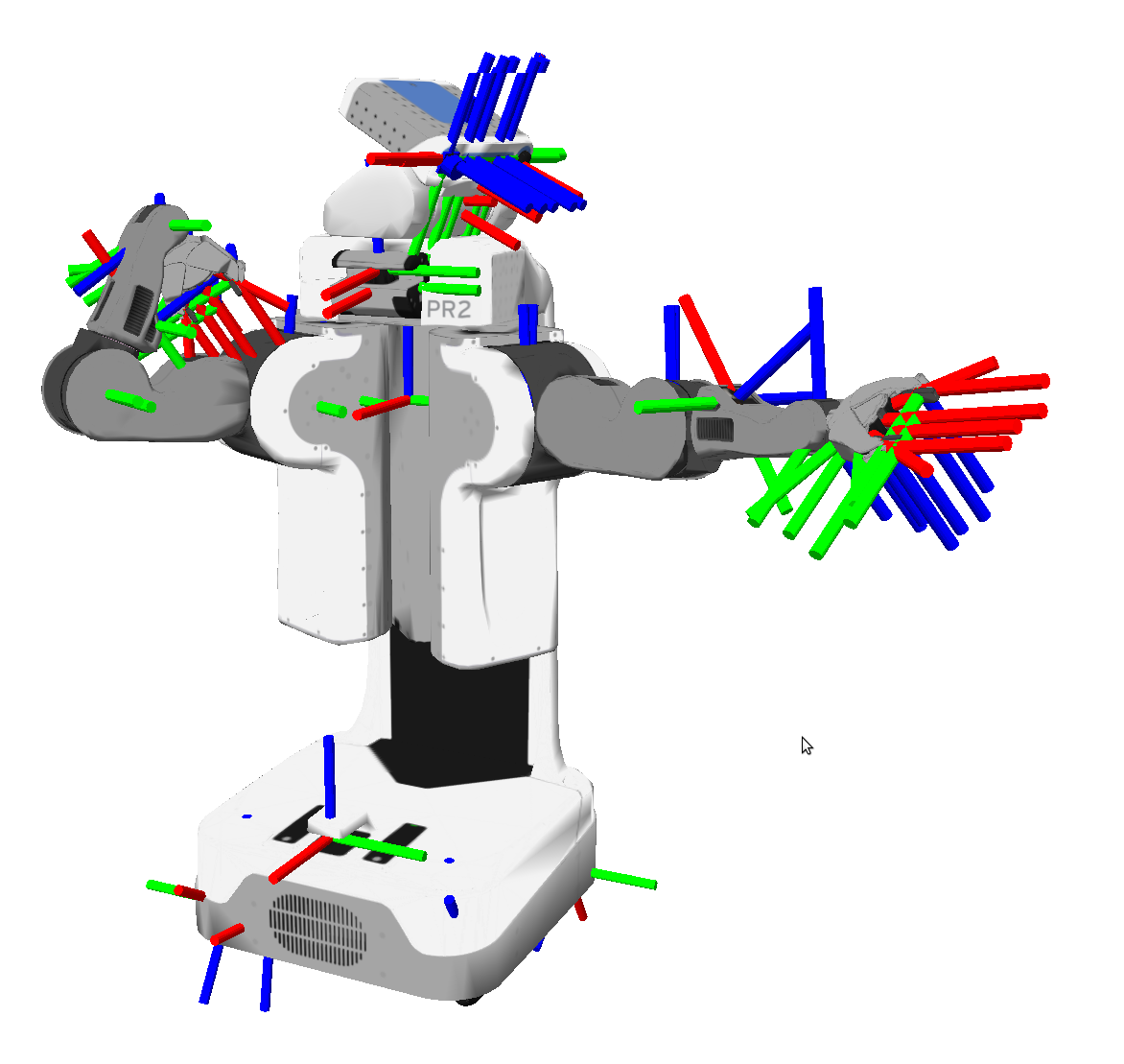
If necessary, press the “Reset” button in the lower right to fresh the display. If everything is correct, you should see a (simple) 3D model of the Mirte Master robot, including a whole bunch of 3D TF frames, like this:
Exercise 6.7
Now that we have a more interesting use case, try to create a pdf graph of the transformation tree using the view_frames tool.
Exercise 6.8
You can use regular ROS2 topic echo tool to subscribe to the joint_states topic, and see what happens when you change the slides in the GUI.
6.5.9. Summary#
We have seen how to use transforms and frame_id to express spatial coordinate frames, and inspect these in RViz.
This should make clear why it is important to properly set the frame_id of a message’s header (if it has one).
One of the most important reasons to learn tf2 however is to use it when you develop your own nodes that need to reason about spatio-temporal events.
This will be covered in a later tutorial.